The relays listed are the ones I most commonly have to point out for various troubleshooting procedures. In your case disregard the IC pump relay and Inertia Switch relay.
I'm not much of an electrician and the proper terminology escaped me at the time I was typing that post. I believe "lead" or "pin" are proper names for the "legs" I referred to in my previous post. They are the male spades on the underside of the relay that plug into the fuse block.
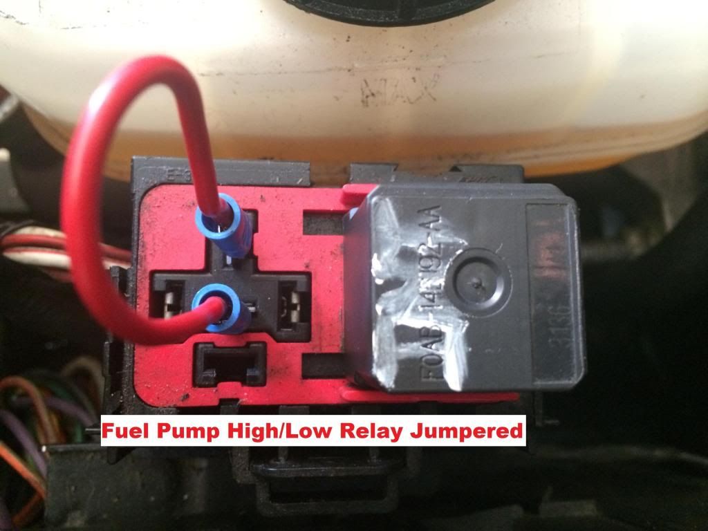
"Jumpering" (bypassing) relays is sometimes necessary when members are troubleshooting fuel pressure and fuel delivery issues. Jumpering the relay consist of removing the appropriate relay and placing a piece of wire between two contacts so an intended function happens. For example, jumpering the high/low relay as shown in the pic below runs the fuel pumps at constant full voltage.
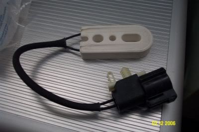
I am not certain of the similarities and differences between the NA F-150 fuel system and the system used in Ls/HDs. Obviously there's the addition of a second fuel pump to meet the added fuel demand. The L/HD system is a return system, I'm not sure if the NA F-150 used a return or non-return system. As I mentioned in my earlier post, the factory L/HD fuel pumps do not run at constant full voltage. Under normal driving conditions some voltage is "bleed off" and released in the form of heat by the drop voltage resister (pictured below). I am willing to bet you do not have a drop voltage resister wired into your fuel system which may explain your current issues. On a L/HD the drop voltage resister is mounted under the front of the truck near the heat exchanger.
When certain conditions (load, MAF, etc.) are met the ECU commands full voltage to the fuel pumps. When this happens the fuel pump high/low relay as I understand bypasses the drop voltage resister so full voltage is sent to the pumps which in turn increases fuel pressure.
Base fuel pressure (FP) per Ford is 39.5 PSI. For sake of ease we usually say 40 PSI is base FP. FP is controlled by the fuel pressure regulator (FPR) which must have both vacuum AND boost references to ensure proper fueling at all times.
-For every 2 In./Hg. of vacuum applied to the FPR the FP will decrease by 1 PSI from the base FP.
Example - If your truck idles at 20 In./Hg. you will subtract 10 PSI off the base FP of 40 (40 PSI - 10 PSI = 30 PSI at idle).
-For every 1 PSI of boost applied to the FPR the FP should rise 1 PSI above the base FP.
Example - If your truck makes 12 PSI boost at WOT you will add 12 PSI to the base 40 PSI (40 + 12 = 52 PSI at WOT)


 Reply With Quote


