From the F150 archives.
Arrogant Bastard :drink: buddy.Originally posted by Silver-Y2K-SVT
Here we go, gang. I'm not looking under the hood now, thus working from memory, so please excuse any generalities.
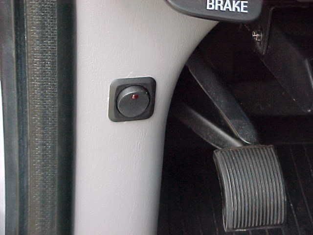
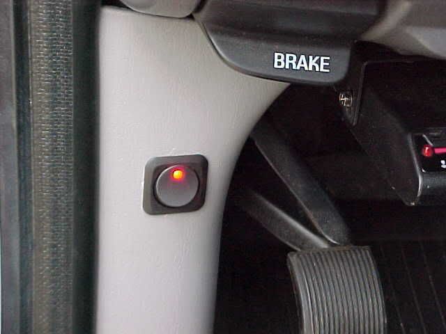
First, you'll need to select a position for mounting the switch and indicator LED. I used the bottom of the cupholder under the stereo head unit. No drinks allowed, so no problem there (8000 miles on the cleanest 2000 model you've ever seen).
You need to get a switch. Specifically, a double-pole double-throw (DPDT) switch. Also, you need to select one that is NOT a "center-off" type. Specifically, one that is either ON position one or ON position two. Most of the automotive switches that you are going to find are "center-off" units, and thus not suitable. I hit the local Radio Shack, and found a couple suitable DPDT switches, all intended for 120/240 V service, none with the high-amperage capability of a typical automotive unit. I got a 10-amp 120 V unit, and it has performed fine. I wouldn't go any lower than that for amperage rating, however.
Basically, the double-throw part means that you have a selector switch (a switch that selects between circuit "A" or circuit "B"). This could mean either a single input going to device "A" or "B", or a single device being driven by input "A" or "B". The latter is our situation - a single device (the IC pump) being driven by a choice of two inputs (either the normal switched supply off the relay or directly from the battery).
The double-pole part means that effectively you have two separate switches bound together in a "gang" - when you throw the switch you effetively throw two electrically independent switches simultaneously. We will use one to drive the IC pump and the other to drive the LED indicator.
You will also need to get a proper LED indicator. Get a surface-mount unit that is properly ballasted (with a resistor) for 12 VDC. If you just geat a bare LED without the resistor, it will have the lifespan of a fruit fly, possibly less.
You also need two fuse holders and two matching 10-amp/12 VDC (or 15-amp) fuses to protect both of the input circuits. We don't want to torch your 'Bolt, do we?
Use good 16-gauge wire or better, solder all of the joints, shrink-tube the joints and friction-tape the WHOLE HARNESS liberally. Do it right, and do it once. A million black zip-ties willl be handy, especially if you're fishing the harness through the firewall. Most importantly, DISCONNECT THE DAMN BATTERY BEFORE YOU DO ANYTHING! Consider yourself warned.
Now for the wiring. Recall, we'll be wiring all of the IC pump stuff off one pole of the switch and the LED stuff off the other pole. Looking at the "back side" of the switch, the contacts for each pole will be three lugs in a row (two rows of three).
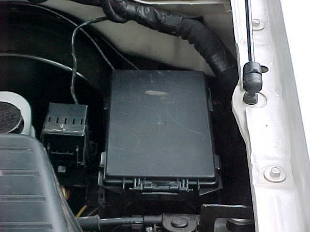
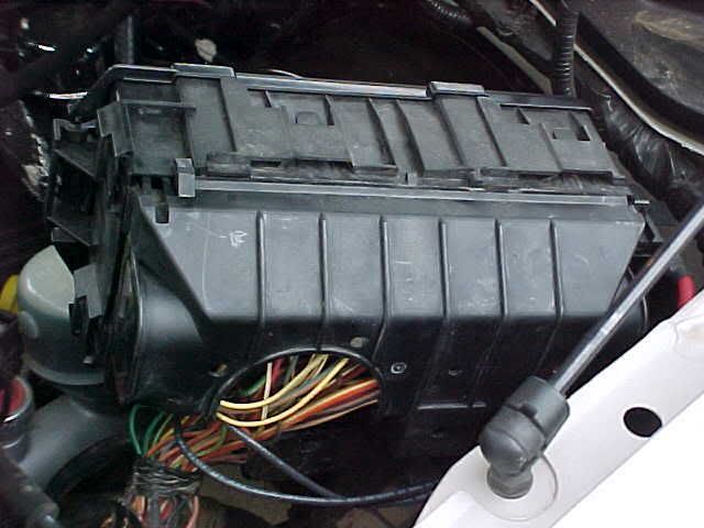
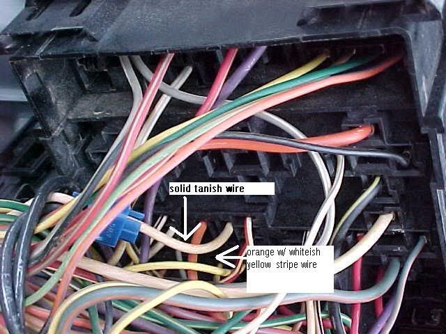
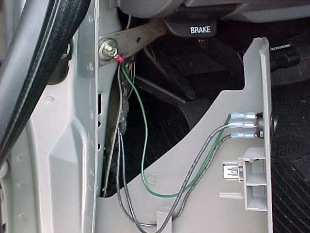
Look at the IC pump. You have a ground wire (black) and a "hot" wire (white or a bit yellow-ish). The "hot" wire can be traced back to the "out" side of a big relay high on the firewall on the passenger's side. You need to cut the "hot" wire to the IC pump at any point that is convenient. The portion of the wire that is still attached to the pump needs to be run to the center lug of the "IC" pole of the switch. This is our single "out" from the switch. In other words, regardless of which position (which "feed") is selected, the output will be to the IC pump.
The other portion of the IC "hot" wire (the portion attached to the "out" side of the relay) needs to be run to one of the two available input lugs on the "IC" pole of the switch. Attach it to the lug corresponding to the position on the switch that you want to be "normal". Now think for a minute - when the switch is in this position, you have just "repaired" the cut in the IC "hot" wire. Simple, right? Also, make sure you wire a fuse in-line on this wire.
Now, from the remaining input lug in the "IC" pole of the switch (on the side of the switch that you want to correspond to "pump running with the engine off"), run a wire (with a fuse wired in-line) to the "in" side of the same relay that the other wire was run off. The "in" side will have a pile of thick wires with ring terminals bolted to a thick threaded lug. Solder an appropritely-sized ring terminal to the wire and bolt it onto the lug on the top of the pile. Make sure that you have the battery disconnected, as this lug is fed directly off the battery and is always hot! Again think - when the switch is in this position, the feed is directly off the battery and direct to the IC pump. The pump will come on instantly when the switch is thrown and will run as long as there is juice in the battery. Thus, with the truck running, the pump will function normally, but you'll be looking for a jump if you forget and leave the switch in this position too long with the truck turned off.
Now for wiring the LED. You will want the LED to be lit when the switch is in the "pump running with engine off" position, as a warning that you will be walking home if you're not careful. Right? Anyway, you again will have three lugs available on the "LED" pole of the switch. We will only be using two. This time, the center lug will be the "feed" (as opposed to the "output" as it was used on the "IC" pole). You need to solder a short jumper wire from the center lug on the "LED" pole to the lug on the "IC" pole corresponding to the wire connected to the "in" side of the relay on the firewall (the "pump running with the with engine off" positin of the switch). Thus, the center lug on the "LED" side of the switch will be always "hot" (always connected to the battery, through a couple of connections). On the remaining lug on the "LED" pole of the switch corresponding to the "pump running with the engine off" switch position, connect one of the two leads from the LED (I think theat the lead with the resistor would be best). The other lead from the LED needs to be connected to a good ground - I prefer to solder directly to an existing black ground wire somewhere under the hood - they are everywhere.
Anyhow, now on the "LED" pole of the switch you have the center lug always hot, and when you flip the switch to the "pump running with engine off" position, you cunnect this 12 VDC source to one of the legs of the LED. The juice passes through the LED and to ground, thus lightting the LED whenever the switch is in this position. In the switch "normal" position, the LED is disconnected from the power.
That's a lot of typing, but I hope that some of you benefit from this. I can tell you that it just about made my head explode working this up from just about zero, with the exception of Noel's rough instructions located via the search function.
This is the only truly proper way to do the job - by "proper", I mean no cutting into the computer harness, no back-feeding juice to the "out" side of the relay, and NO COB JOB WIRES JAMMED INTO THE FUSE BOX.
Bob

 Reply With Quote